CYLINDER LINER
The cylinder liner is a sleeve in which the piston of an engine reciprocates. The life of a cylinder between its re-bores depends two main factors:(i) Abrasion, and (ii) Corrosion
Abrasion depends on the atmospheric con- dition and the efficiency of the air filter and oil filter. Dusty atmospheric air is more harm- ful as it increases abrasion in the cylinder.
Corrosion of the cylinder is caused due the corrosive products of combustion, which are formed after burning of fuel with air. Cor- rosion is accelerated at low cylinder tempera- ture due to acid bearing moisture on the cyl- inder walls,
The use of separate barrels or sleeves, which are known as cylinder liners, provides a long life to the cylinder. These cylinder liners are made of superior material and are fitted in the cylinder block. The liners are removable and can be replaced when worn or damaged. The liners should have good wear resistance and the ability to retain oil to lubricate the surface between the walls and the piston rings.
Materials for Cylinder Liners:
For cylinder liners nickel-chromium iron has been popularly used. The nickel-chromium iron used contains carbon 3.5%; manganese 0.6%: phosphorous 1.5%; sulphur (0.05%; silicon 2%; nickel 2%; and chromium 0.7%.
To increase the wear resistance, the liners are hardened by heating to 855°C-865°C for 30 to 40 minutes and then quenched in oil. By such heat treatment, the life of the liners is increased to three times as compared with grey iron or cast iron cylinders.
Types of Liners
The cylinder liners or sleeves are of two types:
1. Dry liners.
2. Wet liners
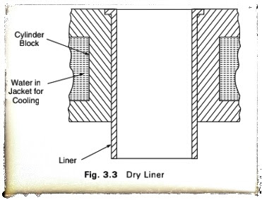
Dry liners are made in the shape of a barrel having a flange the top as shown the Fig. 3.3.
The flange keeps the liner in position in the cylinder block. The liner fits accurately in the cylinder. The perfect contact of the liner with the cylinder block is necessary for the effective cooling liner. Also, the gas pressure, piston thrust and impact load- ing during combustion are resisted by the combined thickness of liner and the cyl- inder. Therefore, dry liners are thinner having wall thickness varying from 1.5 mm to 3 mm and are used mostly for reconditioning worn liners. The dry liners are not in direct contact with cooling water.
2. Wet Liners :
Figure 3.4 shows a wet liner. A wet liner is so called because the cooling water comes in contact with the liner. This liner is provided with a flange at the top, which fits into the groove made in the cylin- der block. To stop leakage of cooling water in the crankcase, the lower end of wet liner is sealed with the help of sealing rings or packing rings.
As the wet liner has to withstand gas pressure, thrust and impact loading, the wall thickness of the liner is increased and is made more than that of the dry liner. Generally, the wall thickness of the wet liner ranges from 3 mm to 6 mm. The outside of the liner is coated with aluminium so that it is protected from rust. The wet liner is better cooled than the dry liner. It is easily removable when it is worn-out or damaged.
Comparison of Dry and Wet Liners:
1. A wet liner can be easily replaced whereas a dry liner requires special tools because it is tight-fitted in the cylinder block.
2. A wet liner is properly cooled as it comes in direct contact with the cooling water, whereas a dry liner does not come in direct contact with the cooling water. Hence the working temperature of a dry liner is more than a wet liner.
3. A wet liner needs leak proof joints, so that the cooling water does not leak into the crankcase, whereas a dry liner has no such requirement.
4. A wet liner does not require accurate finishing on the outside, whereas a dry liner needs accurate finishing.
5. Finishing may be completed in a wet liner before assembly, whereas a dry liner needs finishing after assembly.
PISTON
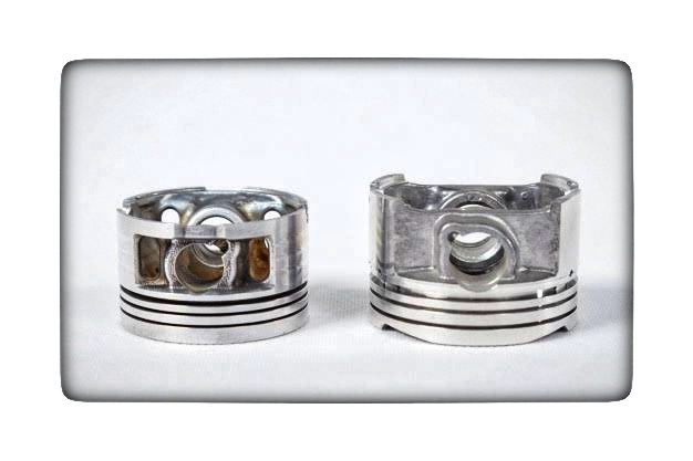
A piston of an internal combustion engine is in the form of an inverted bucket shape and it is free to slide in the cylinder barrel. The gas tightness is secured by means of flexible piston rings, which are in the grooves of the piston. These grooves are cut in the upper part of the piston.A piston of an internal combustion engine serves three functions:
1. It forms a moveable wall of the combustion chamber.
2. It transmits turning force to the crankshaft via the connecting rod.
3. It functions like a crosshead and transmits side thrust, which is due to the angularity of the connecting rods, to the cylinder walls.
The piston must possess the following qualities:
1. It must be strong enough to withstand high pressure caused due to the combustion of fuel.
2. It must be very light in weight to have minimum primary and secondary forces, which are caused due to the inertia forces of the reciprocating masses. A light piston permits higher speed of the crank.
3. The piston material must be a good conductor of heat so that detonation is suppressed, and higher compression ratio is possible to get fuel economy.
It is interesting to know that an engine having a piston and cylinder head of aluminium alloy can be used at a compression ratio of 6.3 and it gives more power and fuel economy than similar engine having a cast iron piston and cylinder head at a compression ratio of 5.3 as shown in Fig. 3.6. This is due to the improved thermal efficiency, which is due to the thermal conductivity of aluminium alloy. Apart from the qualities mentioned previously, the piston must meet the following requirements:
1. The piston operation must not be noisy.
2. The piston must be of less coefficient of expansion.
It has been found by experiments that the maximum temperature produced is in the centre of the piston head, and the temperature decreases towards the edge of the piston head, and also decreases rapidly down side of the piston. Most of the heat is passed into the cylinder block at the ring belt, and some temperature drop takes place from the skirt.
In early years, cast iron pistons were used because of their strength and excellent wearing qualities. However, cast iron has lesser heat conductivity than aluminium alloy and consequently cast iron pistons run hotter than aluminium alloy pistons. Figure 3.7 shows the construction of a piston and the experimental results of piston temperature have been compared between cast iron pistons and aluminium alloy pistons.
In Fig. 3.7, an aluminium alloy piston with a T slot skirt has been shown. 'A' is the head or crown of the piston. In this type of piston, the head grooves are cut to fit the piston rings B'. The piston skirt 'C' functions like a bearing and guiding surface in contact with the cylinder walls. In modern pistons, the length of the skirt is 0.75 to 0.8 times the piston diameter, and the overall length of the piston is from 1.0 to 1.1 times the piston diameter. It is seen that longer skirts do not reduce the rate of cylinder wear. However, piston slap is reduced in pistons with longer skirts because of the effective bearing surface provided. In Fig 3.7, 'D' indicates the bosses inside the skirt. These bosses are for fitting the gudgeon pin 'E' which is across the diameter of the skirt. There is an oil scraper ring 'F which prevents excess oil from reaching the combustion chamber. In some modern pistons the oil ring is provided below the gudgeon pin or the piston pin.


0 comments:
Post a Comment