This is default featured slide 1 title

Go to Blogger edit html and find these sentences.Now replace these sentences with your own descriptions.This theme is Bloggerized by Lasantha Bandara - Premiumbloggertemplates.com.

This is default featured slide 2 title

Go to Blogger edit html and find these sentences.Now replace these sentences with your own descriptions.This theme is Bloggerized by Lasantha Bandara - Premiumbloggertemplates.com.

This is default featured slide 3 title

Go to Blogger edit html and find these sentences.Now replace these sentences with your own descriptions.This theme is Bloggerized by Lasantha Bandara - Premiumbloggertemplates.com.

This is default featured slide 4 title

Go to Blogger edit html and find these sentences.Now replace these sentences with your own descriptions.This theme is Bloggerized by Lasantha Bandara - Premiumbloggertemplates.com.

This is default featured slide 5 title

Go to Blogger edit html and find these sentences.Now replace these sentences with your own descriptions.This theme is Bloggerized by Lasantha Bandara - Premiumbloggertemplates.com.

Sunday, May 30, 2021

WHAT IS A TURBOCHARGER AND HOW DOES IT WORK?What is supercharger/ how supercharger work/ types of superchargers.

 WHAT IS A TURBOCHARGER AND HOW DOES IT WORK?


A turbocharger is a device fitted to a vehicle’s engine that is designed to improve the overall efficiency and increase performance. This is the reason why many auto manufacturers are choosing to turbocharge their vehicles. The new Chevrolet Trax and Equinox are both offered with turbocharged engines and as time goes on, more and more vehicles will be fitted with them.

How does it work ?


A turbo is made up of two halves joined together by a shaft. On one side, hot exhaust gasses spin the turbine that is connected to another turbine which sucks air in and compresses it into the engine. This compression is what gives the engine the extra power and efficiency because as more air can go in the combustion chamber, more fuel can be added for more power.


Watch this video to understand it better


 Supercharger:


       A supercharger is an air compressor that increases the pressure or density of air supplied to an internal combustion engine. This gives each intake cycle of the engine more oxygen, letting it burn more fuel and do work, thus increasing power.

        Power for the supercharger can be provided mechanically by means of a belt, gear, shaft, or chain connected to the engine's crankshaft.


Working of a supercharger
 
      Superchargers are basically compressors/blowers which takes air at normal ambient pressure & compresses it and forcefully pushes it into engine. Power to the compressor/blower is transmitted from engine via the belt drive.

    The addition of extra amount of air-fuel mixture into the cylinder increases the mean effective pressure of the engine. An increment in MEP makes the engine produce more power. In this way, adding a compressor to the engine makes it more efficient.

Types of superchargers:


Centrifugal superchargers
:
    These are commonly used in the vehicles & are powered by the engine via a belt-pulley system. The air-fuel mixture enters the impeller at the centre. The air is then passed through diffuser, which increases the pressure. Finally the air makes it way through the volute casing to the engine.

Root's type supercharger:
      Root's type contain two rotors of epicycloid shape. The rotors are of equal size inter-meshed & are mounted and keyed on 2 different shafts. Any one shaft is powered by the engine via a V-belt or gear train (depending on the distance). Each rotor can have 2 or more than 2 lobes depending upon the requirement. The air enters through the inlet & gets trapped on its way to outlet. As a result, pressure at outlet would be greater than the inlet.


Vane type supercharger:
        A number of vanes are mounted on the drum of the supercharger. These vanes are pushed outwards via pre- compressed springs. This arrangement helps the vane to stay in contact with the inner surface of the body.

       Now due to eccentric rotation, the space between two vanes is more at the inlet & less at the outlet. In this way, the quantity of air which enters at the inlet decreases it's volume on its way to outlet. A decrease in volume results in increment of pressure of air. Thus the mixture obtained at the outlet is at higher pressure than at the inlet.

Advantages of Supercharging:
1. Higher power output. This was whole point of. studying & installing superchargers.

2. Reduced smoke from exhaust gases. The extra. air pushed into cylinder, helps the air to complete combust leading to lesser smoke generation.

3. Quicker acceleration of vehicle. Supercharger starts working as soon as the engine starts running. This way the engine gets a boost even at the beginning leading to quicker acceleration.

4. Cheaper than turbocharger.

Limitations:

• Draws power from engine. Though the overall mechanical efficiency is increased but it consumes power from the engine. The same job is done by a turbocharger without consuming extra power.

• Increased heat generation. The engine should have proper heat dissipation systems as well as it should be able to withstand thermal stresses.

• Induces stress. The engine must hold up against the high pressure & bigger explosions generated in the cylinder. If the engine is not designed considering these stresses, it may damage the piston head.


What is Cylinder liner/ materials for cylinder liners/types of liners/Comparison the LinersWhat is piston/how piston work/piston's functions.


 CYLINDER LINER


        The cylinder liner is a sleeve in which the piston of an engine reciprocates. The life of a cylinder between its re-bores depends two main factors:
 (i) Abrasion, and (ii) Corrosion

        Abrasion depends on the atmospheric con- dition and the efficiency of the air filter and oil filter. Dusty atmospheric air is more harm- ful as it increases abrasion in the cylinder.

        Corrosion of the cylinder is caused due the corrosive products of combustion, which are formed after burning of fuel with air. Cor- rosion is accelerated at low cylinder tempera- ture due to acid bearing moisture on the cyl- inder walls,

   The use of separate barrels or sleeves, which are known as cylinder liners, provides a long life to the cylinder. These cylinder liners are made of superior material and are fitted in the cylinder block. The liners are removable and can be replaced when worn or damaged. The liners should have good wear resistance and the ability to retain oil to lubricate the surface between the walls and the piston rings.

 Materials for Cylinder Liners:
 

       For cylinder liners nickel-chromium iron has been popularly used. The nickel-chromium iron used contains carbon 3.5%; manganese 0.6%: phosphorous 1.5%; sulphur (0.05%; silicon 2%; nickel 2%; and chromium 0.7%.

      To increase the wear resistance, the liners are hardened by heating to 855°C-865°C for 30 to 40 minutes and then quenched in oil. By such heat treatment, the life of the liners is increased to three times as compared with grey iron or cast iron cylinders.


Types of Liners

The cylinder liners or sleeves are of two types:
 1. Dry liners.
 2. Wet liners


1. Dry Liners:

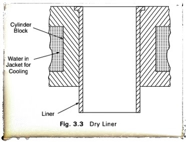
          Dry liners are made in the shape of a barrel having a flange the top as shown the Fig. 3.3.
 
     The flange keeps the liner in position in the cylinder block. The liner fits accurately in the cylinder. The perfect contact of the liner with the cylinder block is necessary for the effective cooling liner. Also, the gas pressure, piston thrust and impact load- ing during combustion are resisted by the combined thickness of liner and the cyl- inder. Therefore, dry liners are thinner having wall thickness varying from 1.5 mm to 3 mm and are used mostly for reconditioning worn liners. The dry liners are not in direct contact with cooling water.


2. Wet Liners :

        Figure 3.4 shows a wet liner. A wet liner is so called because the cooling water comes in contact with the liner. This liner is provided with a flange at the top, which fits into the groove made in the cylin- der block. To stop leakage of cooling water in the crankcase, the lower end of wet liner is sealed with the help of sealing rings or packing rings.

    As the wet liner has to withstand gas pressure, thrust and impact loading, the wall thickness of the liner is increased and is made more than that of the dry liner. Generally, the wall thickness of the wet liner ranges from 3 mm to 6 mm. The outside of the liner is coated with aluminium so that it is protected from rust. The wet liner is better cooled than the dry liner. It is easily removable when it is worn-out or damaged.

Comparison of Dry and Wet Liners:

1. A wet liner can be easily replaced whereas a dry liner requires special tools because it is tight-fitted in the cylinder block.

2. A wet liner is properly cooled as it comes in direct contact with the cooling water, whereas a dry liner does not come in direct contact with the cooling water. Hence the working temperature of a dry liner is more than a wet liner.

3. A wet liner needs leak proof joints, so that the cooling water does not leak into the crankcase, whereas a dry liner has no such requirement.

4. A wet liner does not require accurate finishing on the outside, whereas a dry liner needs accurate finishing.

5. Finishing may be completed in a wet liner before assembly, whereas a dry liner needs finishing after assembly.


 PISTON

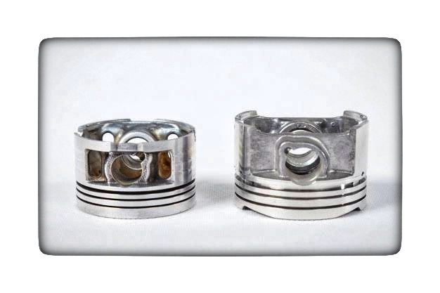
  A piston of an internal combustion engine is in the form of an inverted bucket shape and it is free to slide in the cylinder barrel. The gas tightness is secured by means of flexible piston rings, which are in the grooves of the piston. These grooves are cut in the upper part of the piston.

A piston of an internal combustion engine serves three functions:

1. It forms a moveable wall of the combustion chamber.

2. It transmits turning force to the crankshaft via the connecting rod.

3. It functions like a crosshead and transmits side thrust, which is due to the angularity of the connecting rods, to the cylinder walls.

The piston must possess the following qualities:

1. It must be strong enough to withstand high pressure caused due to the combustion of fuel.

2. It must be very light in weight to have minimum primary and secondary forces, which are caused due to the inertia forces of the reciprocating masses. A light piston permits higher speed of the crank.

3. The piston material must be a good conductor of heat so that detonation is suppressed, and higher compression ratio is possible to get fuel economy.

       It is interesting to know that an engine having a piston and cylinder head of aluminium alloy can be used at a compression ratio of 6.3 and it gives more power and fuel economy than similar engine having a cast iron piston and cylinder head at a compression ratio of 5.3 as shown in Fig. 3.6. This is due to the improved thermal efficiency, which is due to the thermal conductivity of aluminium alloy. Apart from the qualities mentioned previously, the piston must meet the following requirements:

1. The piston operation must not be noisy.

2. The piston must be of less coefficient of expansion.

     It has been found by experiments that the maximum temperature produced is in the centre of the piston head, and the temperature decreases towards the edge of the piston head, and also decreases rapidly down side of the piston. Most of the heat is passed into the cylinder block at the ring belt, and some temperature drop takes place from the skirt.


       In early years, cast iron pistons were used because of their strength and excellent wearing qualities. However, cast iron has lesser heat conductivity than aluminium alloy and consequently cast iron pistons run hotter than aluminium alloy pistons. Figure 3.7 shows the construction of a piston and the experimental results of piston temperature have been compared between cast iron pistons and aluminium alloy pistons.

        In Fig. 3.7, an aluminium alloy piston with a T slot skirt has been shown. 'A' is the head or crown of the piston. In this type of piston, the head grooves are cut to fit the piston rings B'. The piston skirt 'C' functions like a bearing and guiding surface in contact with the cylinder walls. In modern pistons, the length of the skirt is 0.75 to 0.8 times the piston diameter, and the overall length of the piston is from 1.0 to 1.1 times the piston diameter. It is seen that longer skirts do not reduce the rate of cylinder wear. However, piston slap is reduced in pistons with longer skirts because of the effective bearing surface provided. In Fig 3.7, 'D' indicates the bosses inside the skirt. These bosses are for fitting the gudgeon pin 'E' which is across the diameter of the skirt. There is an oil scraper ring 'F which prevents excess oil from reaching the combustion chamber. In some modern pistons the oil ring is provided below the gudgeon pin or the piston pin.

Friday, May 21, 2021

Basic Parts of the Gasoline Engine are listed below/Why not diesel engines are not preferred in commercial?/Advantages diesel engines.

Basic Parts of the Gasoline Engine:


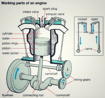
Basic Parts of the Gasoline Engine are listed below:


1. Cylinder block
2. Piston
3. Piston rings
4. Piston pin
5. Connecting rod
6. Crankshaft
7. Cylinder head
8. Intake valve
9. Exhaust valve
10. Camshaft
11. Timing gears
12. Spark plug

Cylinder Block:
      Cylinder Block is the Basic frame of gasoline engine. Contains the cylinder.

Piston:
      Piston is a sliding plug that harnesses the force of the burning gases in the cylinder.

Piston Rings:
      Piston rings seal the compression gases above the piston keep the oil below the piston rings.

Piston Pins:
      Piston Pins Also known as the wrist pin, it connects the piston to the small end of the connecting rod. It transfers the force and allows the rod to swing back and forth.

Connecting Rod:
      Connecting Rod Connects the piston and piston pin to the crankshaft.

Crankshaft:
      Crankshaft Along the piston pin and connecting rod it converts the up and down motion (reciprocating) of the engine to spinning (rotary) motion.

Flywheel:
     Flywheel Carries the inertia when there is no power stroke.

Cylinder Head:
     Cylinder Head Forms the top of the combustion chamber. Contains the valves, the passage ways for the fuel mixture to move in and out of the engine.

Intake and Exhaust Valves:
      Intake and Exhaust Valves Doorway that lets the gases in and out of the engine.

Camshaft:
      Camshaft Through the use of an eccentric the cam lobes push the valves open. The valve springs close them.

Timing Gears:
       Timing Gears These gears drive the camshaft from the crankshaft.

Fly Wheel:
      The net torque imparted to the crankshaft during one complete cycle of operation of the engine fluctuates causing a change in the angular velocity of the shaft. In order to achieve a uniform torque an inertia mass in the form of a wheel is attached to the output shaft and this wheel is called the flywheel.

Why not diesel engines are not preferred in commercial?:


1. Diesel engines, because they have much higher compression ratios (20:1 for a typical diesel vs. 8:1 for a typical gasoline engine), tend to be heavier than an equivalent gasoline engine.

2. Diesel engines also tend to be more expensive.

3. Diesel engines, because of the weight and compression ratio, tend to have lower maximum RPM ranges than gasoline engines. This makes diesel engines high torque rather than high horsepower, and that tends to make diesel cars slow in terms of acceleration.

4. Diesel engines must be fuel injected, and in the past fuel injection was expensive and less reliable

5. Diesel engines tend to produce more smoke.

6. Diesel engines are harder to start in cold weather, and if they contain glow plugs, diesel engines can require you to wait before starting the engine so the glow plugs can heat up.

7. Diesel engines are much noisier and tend to vibrate.

8. Diesel fuel is less readily available than gasoline

Advantages diesel engines:


       The two things working in favour of diesel engines are better fuel economy and longer engine life. Both of these advantages mean that, over the life of the engine, you will tend to save money with a diesel.
    
      However, you also have to take the initial high cost of the engine into account. You have to own and operate a diesel engine for a fairly long time before the fuel economy overcomes the increased purchase price of the engine.

     The equation works great in a big diesel tractor-trailer rig that is running 400 miles every day, but it is not nearly so beneficial in a passenger car.

Thursday, May 20, 2021

Components of an Engine/Terms connected with i.c. engines/Definition of ‘Engine’/Engine Components.

Components of an Engine:

        Even though reciprocating internal combustion engines look quite simple, they are highly complex machines. There are hundreds of components that have to perform their functions satisfactorily to produce output power. There are two types of engines, viz., spark ignition (S1) and compression-
ignition (CI) engine. Let us now go through the important engine components and the nomenclature associated with an engine.

Terms connected with i.c. engines:


1. Bore: The inside diameter of the cylinder is called bore

2. Stroke: The linear distance along the cylinder axis between two limiting position s is called stroke.

3. Top Dead Center (T.D.C.): the top most position of the piston towards cover end side of the cylinder is called T.D.C.

4. Bottom dead Center (B.D.C.): The lowest position of the piston towards the crank end side of the cylinder is called B.D.C.

5. Clearance Volume: The volume contained in the cylinder above the top of the piston, when the piston is at top dead center, is called the clearance volume.

6. Swept Volume: The volume swept through by the piston in moving between T.D.C. and B.D.C, is called swept volume or piston displacement.

7. Compression Ratio: It is the ratio of Total cylinder volume to clearance volume

Definition of ‘Engine’


       An engine is a device, which transforms one form of energy into another form. Normally, most of the engines convert thermal energy into mechanical work and therefore they are called ‘heat engines’.

Engine Components:

     The major components of the engine and their functions are briefly described below.

Cylinder Block:

     The cylinder block is the main supporting structure for the various components. The cylinder of a multi cylinder engine is cast as a single unit, called cylinder block. The cylinder head is mounted on the cylinder block.
    
     The cylinder head and cylinder block are provided with water jackets in the case of water-cooling with cooling fins in the case of air- cooling. Cylinder head gasket is incorporated between the cylinder block and cylinder head. The cylinder head is held tight to the cylinder block by number of bolts or studs. The bottom portion of the cylinder block is called crankcase. A cover called crankcase, which becomes a sump for lubricating oil is fastened to the bottom of the crankcase. The inner surface of the cylinder block, which is machined and finished accurately to cylindrical shape, is called bore or face.

Cylinder:

    As the name implies it is a cylindrical vessel or space in which the piston makes a reciprocating motion. The varying volume created in the cylinder during the operation of the engine is filled with the working fluid and subjected to different thermodynamic processes. The cylinder is supported in the cylinder block.

Piston:

    It is a cylindrical component fitted into the cylinder forming the moving boundary of the combustion system. It fits perfectly (snugly) into the cylinder providing a gas-tight space with the piston rings and the lubricant. It forms the first link in transmitting the gas forces to the output shaft.

Combustion Chamber:

       The space enclosed in the upper part of the cylinder, by the cylinder head and the piston top during the combustion process, is called the combustion chamber. The combustion of fuel and the consequent release of thermal energy results in the building up of pressure in this part of the cylinder.

Inlet Manifold:

      The pipe which connects the intake system to the inlet valve of the engine and through which air or air-fuel mixture is drawn into the cylinder is called the inlet manifold.


Gudgeon Pin:

      It forms the link between the small end of the connecting rod and the piston.

Exhaust Manifold:

     The pipe that connects the exhaust system to the exhaust valve of the engine and through which the products of combustion escape into the atmosphere is called the exhaust manifold.
 Inlet and Exhaust Valves
       Valves are commonly mushroom shaped poppet type. They are provided either on the cylinder head or on the side of the cylinder for
regulating the charge coming into the cylinder (inlet valve) and for discharging the products of combustion (exhaust valve) from the cylinder.
Connecting Rod It interconnects the piston and the crankshaft and transmits the gas forces from the piston to the crankshaft. The two ends of the connecting rod are called as small end and the big end. Small end is connected to the piston by gudgeon pin and the big end is connected to the crankshaft by crankpin.

Crankshaft:

       It converts the reciprocating motion of the piston into useful rotary motion of the output shaft. In the crankshaft of a single cylinder engine
there is pair of crank arms and balance weights. The balance weights are provided for static and dynamic balancing of the rotating system. The crankshaft is enclosed in a crankcase.

Piston Rings:

    Piston rings, fitted into the slots around the piston, provide a tight seal between the piston and the cylinder wall thus preventing leakage of combustion gases

Camshaft:

    The camshaft and its associated parts control the opening and closing of the two valves. The associated parts are push rods, rocker arms, valve springs and tappets. This shaft also provides the drive to the ignition system. The camshaft is driven by the crankshaft through timing gears.

Cams:

    These are made as integral parts of the camshaft and are designed in such a way to open the valves at the correct timing and to keep them open for the necessary duration.


Wednesday, May 19, 2021

Resistances to vehicle motion and need for a gearbox/Aerodynamics/Fundamental Concept

 Resistances to vehicle motion and need for a gearbox

Aerodynamics:


      Aerodynamics is a branch of dynamics concerned with studying the motion of air, particularly when it interacts with a solid object, such as an airplane wing.

       Aerodynamics is a sub-field of fluid dynamics and gas dynamics, and many aspects of aerodynamics theory are common to these fields. The term aerodynamics is often used synonymously with gas dynamics, with the

difference being that "gas dynamics" applies to the study of the motion of all gases, not limited to air.

Modern aerodynamics only dates back to the seventeenth century, but aerodynamic forces have been harnessed by humans for thousands of years in sailboats and windmills, and images and stories of flight appear throughout recorded history, such as the Ancient Greek legend of Icarus and Daedalus. Fundamental concepts of continuum,drag,and pressure gradients,appear in the work of Aristotle and Archimedes.

Fundamental Concept:


       Understanding the motion of air around an object (often called a flowfield) enables the calculation of forces and moments acting on the object. In many aerodynamics problems, the forces of interest are the fundamental forces of flight: lift, drag, thrust, and weight. Of these, lift and drag are
aerodynamic forces, i.e. forces due to air flow over a solid body.

      Calculation of these quantities is often founded upon the assumption that the flow field behaves as a continuum. Continuum flow fields are characterized by properties such as velocity, pressure, density and temperature, which may be functions of spatial position and time.


      These properties may be directly or indirectly measured in aerodynamics experiments, or calculated from equations for the conservation of mass, momentum, and energy in air flows. Density, velocity, and an additional property, viscosity, are used to classify flow fields.

Tuesday, May 18, 2021

Vehicle construction and Components /vehicle frames, chassis, body, power unit, transmission system/vehicle frame types body types

 Vehicle construction and Components:  

       The main components of an automobile refer to the following components:

Frame,

Chassis,

Body,

Power unit,

Transmission system.


An automobile is made up of mainly two units, these are Chassis and Body.

“Frame” + “Base components” = “Chassis”
“Chassis” + “Body” = “Vehicle”

Frame:

The frame is the skeleton of the vehicle. It serves as a main foundation and base for alignment for the chassis.

Types:


1. Conventional frame

2. Semi integral frame

3. Integral or untidiest frame.

Chassis:

      If the frame contains the base components its called as chassis. The components are like Engine, radiator, clutch, gearbox, silencer, road wheels, fuel tank, wirings, differential units, etc..,

Body:

    Body is the superstructure of the vehicle and it is bolted to the chasis.

Types:

1. Car,

2. Truck,

3. Tractor,

4. Delivery van,

5. Jeep,

6. Bus, etc..,

Introduction of Automobile or vehicle / types of Automobile

 Introduction of Automobile or Vehicle:


              An Automobile is a self propelled vehicle which contains the power source for its propulsion and is used for carrying passengers and goods on the ground, such as car, bus, trucks, etc...,

Types of Automobile:


             The automobiles are classified by the following ways,


1. On the Basis of Load:


A). Heavy transport vehicle (HTV) or heavy motor vehicle (HMV),

B). Light transport vehicle (LTV), Light motor vehicle (LMV),


2. On the Basis of wheels:


A). Two wheeler vehicle, for example: Scooter, motorcycle, scooty, etc.

B). Three wheeler vehicle, for example: Auto rickshaw.

C). Three wheeler scooter for handicaps and tempo, etc.

D). Four wheeler vehicle, for example: Car, jeep, trucks, buses, etc.

E). Six wheeler vehicle, for example: Big trucks with two gear axles.


3. On the basis of Fuel Used:
 

A). Petrol vehicle, e.g. motorcycle, scooter, cars, etc.

B). Diesel vehicle, e.g. trucks, buses, etc.

C). Electric vehicle which use battery to drive.

D). Steam vehicle, e.g. an engine which uses steam engine. Gas vehicle, e.g. LPG and CNG vehicles, where LPG is liquefied


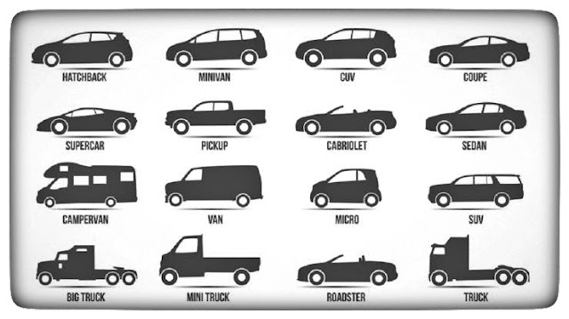
4. On the basis of body style:

 
A). Sedan Hatchback car.

B). Coupe car Station wagon Convertible.

C). Van Special purpose vehicle, e.g. ambulance, milk van, etc.


5. On the basis of Transmission:


A). Conventional vehicles with manual transmission, e.g. car with 5 gears.

B). Semi-automatic

C). Automatic: In automatic transmission, gears are not required to be changed manually.


6. On the basis of Drive:

 
A). Left hand drive

B). Right hand drive


7. On the basis of Driving Axle:


A). Front wheel drive

B). Rear wheel drive

C). All wheel drive


8. Position of Engine:


A). Engine in Front - Most of the vehicles have engine in the front.
 
B). Engine in the Rear Side Very few vehicles have engine located in the rear.

Example: Nano cars.